Product Description
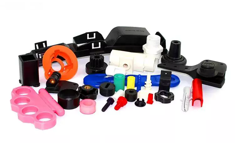
Customized Molded Moulding Nylon PA6 Small Motor Plastic POM Gear Molding Parts
Product Parameters
|
Material |
PA, POM, ABS, PP, PET, PC, PE, HDPE, PA66+GF, PVC, TPFE…. |
|
Color |
Depends on customer’s requirements. |
|
Support Software: |
Pro-E , UGS , SolidWorks ,AutoCAD |
|
Soft ware |
CAD/IGS /STEP/STP /PDF |
|
A surface request |
glossy ,texture |
|
Mold life |
50,000-3000,000 times |
|
Smaple : |
Free sample ! |
|
Delivery time : |
15 days production, if opening mould, plus 15-20 days. |
|
MIN Quantity: |
1000pcs |
|
Package : |
Carton and Pallet , exact part with package every pc . |
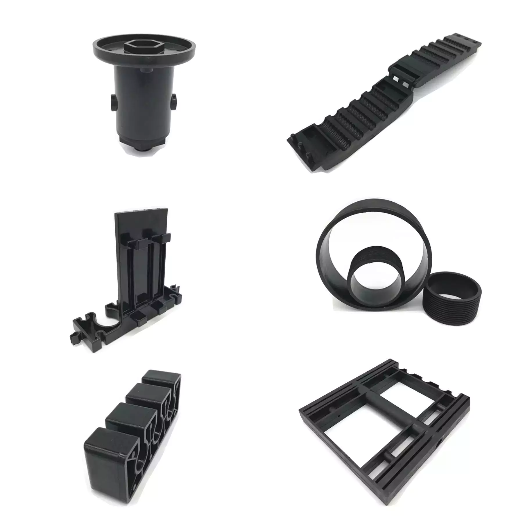
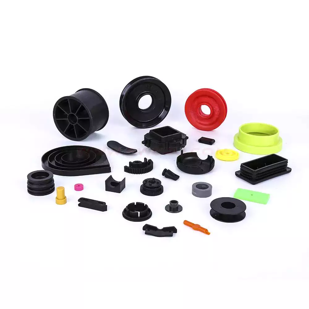
Detailed Photos
About Injection Molding
Injection molding is the most common modern method of manufacturing plastic parts. It is used to create a variety of parts with different shapes and sizes, and it is ideal for producing high volumes of the same plastic part. Injection molding is widely used for manufacturing a variety of parts, from the smallest medical device component to entire body panels of cars. A manufacturing process for producing plastic parts from both thermoplastic and thermosetting materials, injection molding can create parts with complex geometries that many other processes cannot.
Other products
Production process
Company Profile
ZheJiang (HangZhou) Xihu (West Lake) Dis.xin Metal Products Co., Ltd is specialized in the production of aluminum die casting, zinc alloy die casting, and aluminum lightweight production. Since establish of 2006, we always provide the best die casting parts to customers, and now we also develop the lightweight process successfully and obtain many national patents. Our products are widely used in automobile, medical, power Industry, electrical appliance, construction, high-speed railway and so on. And we have exported to Japan, Germany, USA, Canada, Australia and many countries.
Environmental Impact Assessment & ISO 9001 Certied
Selecting a reliable and qualified partner is more different & difficult than just choosing a supplier. We have obtained the license of EIA from government and get certied of ISO 9001, and we will always process our production per as EIA & ISO requirement strictly, to guarantee the stable production, to supply the qualified parts to you and enlarge your business finally. We sincerely hope we can become your faithful partner and develop a flouring future with you.
Certifications
Packaging & Shipping
FAQ
1.Are you a manufacturer or a trading company?
We are a 3000-square-meter factory located in ZheJiang , China.
2.How can I get a quote?
Detailed drawings(PDF/STEP/IGS/DWG…) with material, quantity and surface treatment information.
3. Can I get a quote without drawings?
Sure, we appreciate to receive your samples, pictures or drafts with detailed dimensions for accurate quotation.
4.Will my drawings be divulged if you benefit?
No, we pay much attention to protect our customers’ privacy of drawings, signing NDA is also accepted if need.
5. Can you provide samples before mass production?
Sure, sample fee is needed, will be returned when mass production if possible.
6. How about the lead time?
Generally, 1-2 weeks for samples, 3-4 weeks for mass production.
7. How do you control the quality?
(1)Material inspection–Check the material surface and roughly dimension
(2) Production first inspection–To ensure the critical dimension in mass production
(3)Sampling inspection–Check the quality before sending to the warehouse
(4)Pre-shipment inspection–100% inspected by QC assistants before shipment
8. What will you do if we receive poor quality parts?
Please kindly send us the pictures, our engineers will find the solutions and remake them for you asap.
|
US $0.1-0.3 / Piece | |
100 Pieces (Min. Order) |
###
| Material: | Plastic |
|---|---|
| Application: | Medical, Household, Electronics, Automotive, Agricultural |
| Certification: | RoHS, ISO |
| Name: | Plastic Injection Molded Products |
| Product: | Household Product |
| Material Available: | ABS, PC, PA, PP, POM.Nylon66, etc |
###
| Samples: |
US$ 3/Piece
1 Piece(Min.Order) |
|---|
###
| Customization: |
Available
|
|---|
###
|
Material
|
PA, POM, ABS, PP, PET, PC, PE, HDPE, PA66+GF, PVC, TPFE….
|
|
Color
|
Depends on customer’s requirements.
|
|
Support Software:
|
Pro-E , UGS , SolidWorks ,AutoCAD
|
|
Soft ware
|
CAD/IGS /STEP/STP /PDF
|
|
A surface request
|
glossy ,texture
|
|
Mold life
|
50,000-3000,000 times
|
|
Smaple :
|
Free sample !
|
|
Delivery time :
|
15 days production, if opening mould, plus 15-20 days.
|
|
MIN Quantity:
|
1000pcs
|
|
Package :
|
Carton and Pallet , exact part with package every pc .
|
|
US $0.1-0.3 / Piece | |
100 Pieces (Min. Order) |
###
| Material: | Plastic |
|---|---|
| Application: | Medical, Household, Electronics, Automotive, Agricultural |
| Certification: | RoHS, ISO |
| Name: | Plastic Injection Molded Products |
| Product: | Household Product |
| Material Available: | ABS, PC, PA, PP, POM.Nylon66, etc |
###
| Samples: |
US$ 3/Piece
1 Piece(Min.Order) |
|---|
###
| Customization: |
Available
|
|---|
###
|
Material
|
PA, POM, ABS, PP, PET, PC, PE, HDPE, PA66+GF, PVC, TPFE….
|
|
Color
|
Depends on customer’s requirements.
|
|
Support Software:
|
Pro-E , UGS , SolidWorks ,AutoCAD
|
|
Soft ware
|
CAD/IGS /STEP/STP /PDF
|
|
A surface request
|
glossy ,texture
|
|
Mold life
|
50,000-3000,000 times
|
|
Smaple :
|
Free sample !
|
|
Delivery time :
|
15 days production, if opening mould, plus 15-20 days.
|
|
MIN Quantity:
|
1000pcs
|
|
Package :
|
Carton and Pallet , exact part with package every pc .
|
Benefits of Injection Molded Parts in Design
Injection molded parts are manufactured from a variety of plastics. You can order samples of your desired product or download CAD drawings free of charge. For more information, visit our product catalog. There are numerous benefits of using injection molded products in your designs. Here are some of them. Injection molded products are cost-effective and highly customizable.
Design for manufacturability
 Design for manufacturability (DFMA) is an important part of the design process for injection-molded parts. This process helps to minimize costs and streamline the production process. It also helps in the prevention of problems during the manufacturing process. The process involves several steps that include part geometry, location of critical surfaces, material selection, and dimensioning. It is also crucial to consider the colors and tolerances, which can help to minimize scrap rates.
Design for manufacturability is a vital early stage in the development process to ensure that the product is cost-effective and repeatable. It begins with a thorough understanding of the purpose for which the part is intended. The design process should take into account every aspect of the part, including the material section, tool design, and the production process.
DFM includes guidelines to ensure that the design meets the manufacturing requirements. These guidelines can include good manufacturing practices, as well as good design principles. Good design focuses on the quantity and quality of parts, as well as the complexity of their surfaces and tolerances. The process also focuses on mechanical and optical properties.
Injection molding design for manufacturability can save resources and time. It also reduces the costs of assembly. An injection molder conducts a detailed analysis of these design elements before starting the tooling process. This is not a standalone principle; it should be used in conjunction with other design optimization techniques.
Ideally, a product should be designed for optimum manufacture. This means that it should not have too many parts, or too few. To minimize this, the designer should choose a model that is easy to mold. Also, a design that does not require too many machine operations and minimizes risks.
Plastics used in injection molding
 Injection molding is a very versatile process that uses various types of plastic polymers. These plastics are extremely flexible and can be molded to take on any shape, color, and finish. They can also be customized to contain design elements, text, and safety instructions. Plastics are also lightweight, easily recycled, and can be hermetically sealed to prevent moisture from getting into the product.
Plastics are categorized according to their properties, which can be helpful in selecting the right plastic for a particular application. Different materials have different degrees of hardness, which is important when it comes to molding applications. Some are harder than others, while others are more flexible. Plastics are ranked according to their Shore hardness, which was developed by CZPT.
Polystyrene is one of the most common plastics used in injection molding. However, it has a few disadvantages. While it is a good choice for simple products that do not require high strength and are prone to breakage, it is not ideal for items that need to be resistant to heat and pressure.
While many types of plastics are used in injection molding, choosing the right material is very important. The right material can make a big difference in the performance of your product and the cost of your product. Make sure to talk with your injection molding supplier to determine which plastic is right for your project. You should look for a plastic with a high impact rating and FDA approval.
Another commonly used plastic is PMMA, or polystyrene. This plastic is affordable and has a glass-like finish. It is often used for food and beverage packaging and can be easily recycled. This material is also used in textiles.Characteristics of polypropylene
Polypropylene injection molded parts offer an array of benefits, including a high degree of rigidity, excellent thermal stability, low coefficient of friction, and chemical resistance. These plastics are available in two main types, homopolymers and copolymers. Both types offer superior hardness and tensile strength. However, the material does not have the same fire-resistance as PE plastics.
Polypropylene is a colorless, odorless, crystalline solid. It is highly resistant to a variety of chemicals and is shatter-resistant. Its properties make it a great choice for many industrial applications, including packaging and containers for liquids. The material is also highly durable and can last for a very long time without breaking. In addition, it does not absorb or retain moisture, making it ideal for outdoor and laboratory applications.
Polypropylene is widely used for injection molding, and its low cost, flexibility, and resistance to chemical attack make it a popular choice. This material is also a great electrical insulator and has excellent thermal expansion coefficient. However, it is not biodegradable. Luckily, it can be recycled.
During the molding process, the temperature of the mold is a significant factor. Its morphology is related to the temperature and flow field, and a clear correlation between the two factors is essential. If you can control the temperature and flow, you can optimize your manufacturing process and eliminate costly trial-and-error procedures.
Polypropylene is an excellent electrical insulator and has a high dielectric coefficient. It can also be sterilized and resist high temperatures. Although it is less rigid than polyethylene, it is a good choice for applications where electrical insulation is necessary.
Texture of injection molded parts
 Texture design is a common feature of injection molded parts, which helps to raise the perceived value of the vehicle. While traditional manufacturing processes can produce limited textures, additive manufacturing allows for infinite designs. For example, a design that looks like a wood grain pattern may be printed on an aluminum car part.
Texture is important because it can improve the strength of the part and enhance its adhesion to other surfaces. Moreover, textured parts can resist damage from contact and fingerprints. This makes them more durable and a good option for further molding operations. Injection molding processes usually follow a set of standards from the Society of Plastics Industry, which define different types of surface finishes.
Textured plastic injection molded parts may have various types of surfaces, including wood grain, leather, sand, or stipple. Choosing the right surface texture is crucial for enhancing the appearance of the part, but it must also be compatible with its function. Different materials have different chemical and physical properties, which can influence the type of texture. Moreover, the melting temperature of the material is important for its surface finish. The additives used in the process can also have an impact on the surface finish.
Texture can also vary between manufacturers and types of components. Some textures are flat, while others are rough. The top row corresponds to A3 and B4 in flatness, while the bottom row shows rough surfaces. These rough surfaces may damage sensitive testing equipment. However, some textures may have near equivalence with each other, namely SPI D-3 and MT-11020.
The type of texture that is applied to injection molded parts can affect the minimum draft angle required for the parts to be ejected. Parts with light texture tend to be smoother than parts with heavy textures, while parts with heavy textures require a higher draft angle. The draft angle for heavy textures should be between five and 12 degrees. It is best to consider this early in the design process and consult with the injection molder to get a good idea of the necessary draft angles.

editor by czh2022-11-28
 When developing a medical device, there are several design considerations to be made to create a quality injection molded part. Typically, product designers want to minimize the amount of material needed to fill the part while still maintaining the structural integrity of the product. To this end, injection molded parts often have ribs to stiffen the relatively thin walls. However, improper placement of ribs or projections can create molding problems.
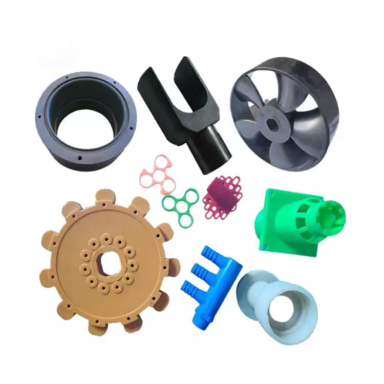 Injection molded parts exhibit a range of mechanical and physical properties. These properties affect the performance of the parts. For example, they can affect electrical conductivity. Also, the degree of filling in the parts can determine their mechanical properties. Some studies have even found that filling content can affect the dimensional accuracy of the parts.
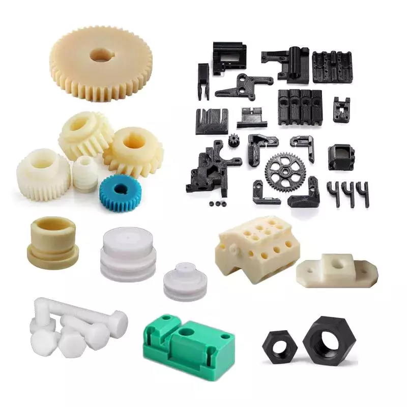 Injection molded parts often use fasteners for securing fastener elements in place. As shown in FIGS. 7 and 8 (two separate views), the fastener elements are integrated with the molded product, and they extend from one side. The fastener elements are designed to engage loop elements in the overlying layer. The palm-tree shaped fasteners are especially well-suited for this purpose, as their three-dimensional sides engage more loops than flat sides. These features result in a more secure closure.
 When designing injection molded parts, it’s essential to consider the wall thickness of the part. Ideally, the wall thickness is uniform across the entire part. This allows the entire mold cavity to fill without restriction, and reduces the risk of defects. Parts that don’t have uniform wall thickness will have high stresses at the boundary between two sections, increasing the risk of cracks, warping, and twisting. To avoid such stresses, designers can consider tapering or rounding the edges of the part to eliminate stress concentration.
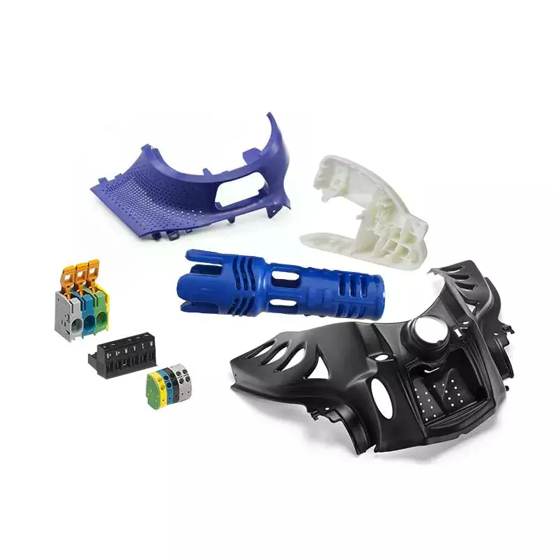 There are two main types of runner systems: hot runner systems and cold runner systems. In a hot runner system, a runner nozzle delivers the molten plastic into the mold cavity. A cold runner system does not require the use of a nozzle and acts as a conduit for the molten plastic.
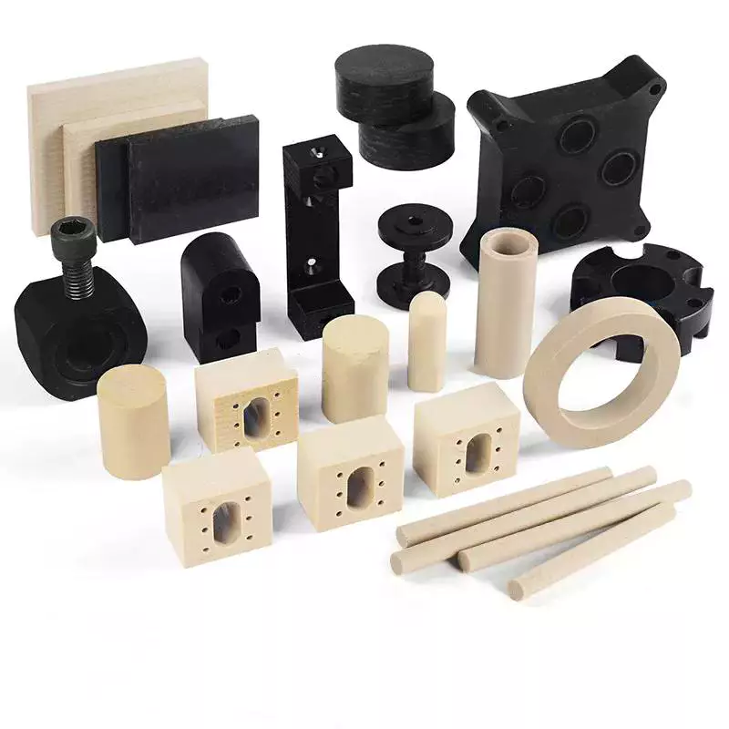 Thermostatic control of temperature in an injection molding process can make a significant impact on part quality. High mold temperatures should be regulated by using a temperature-controlled cooling unit. These devices are equipped with pumping systems and internal heaters. The temperature of the injected plastic determines the plastic’s flow characteristics and shrinkage. Temperature also influences the surface finish, dimensional stability, and physical properties of the finished product.


